The main intention of acquiring the processor was to ensure I have a ready means to process my large supply of expired film. I was initially worried that 16mm film processing will become harder to obtain in Australia into the future, requiring me to send film to the Northern Hemisphere, either Europe or North America, to get processed. Doing so is not overly expensive, however the courier costs are! Thankfully Australia still has Neglab and Nanolab processing 16mm film for the foreseeable future. So now the processor has turned into a project to salvage a high quality film processor from being potentially scrapped, to renovate it, maintain it, and get it running in the event I want to process my own film shooting experiments.
FilmLab processor history:
The company, FilmLab Engineering, was a Sydney based company that build many film processors of varying sizes and capacity for the international market as well as local Australian businesses, from high speed processors capable of up to 100 feet per minute to slow B&W processors capable of as little as 15 feet per minute.
From the research I conducted about this processor, I managed to find out that it is a slow B&W processor built for the National Film & Sound Archives in Canberra about 35 years ago (late 1980’s to 1990’s). The processor was later sold to a film processing lab in Sydney. Around late 2015 it was then sold to a Victorian processing lab, and after a few years of inactivity was sold to a private film processor in Melbourne.
December 2022 update
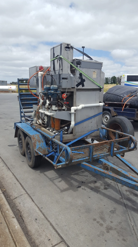
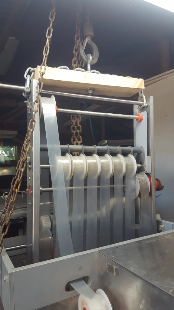
The Filmlab Engineering B&W processor was purchased and collected from Melbourne, Australia. Due to the size and weight, we had to use a bobcat trailer, wooden ramps, 2 ton block and tackle, and winches. We also hired a 4WD ute to pull the heavy trailer approximately 200kms to where it will be housed.
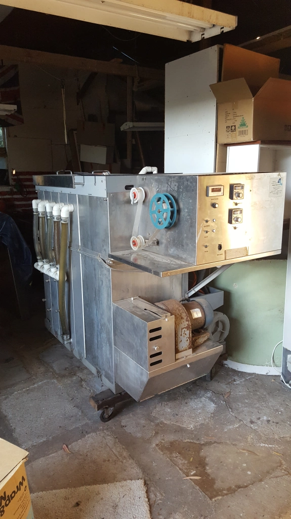
After a very long day the processor was unloaded and placed into a large shed. Once the processor gets running, it will be housed in a dust and light proof room.

A top down picture of the processing tanks, from the left: developer, wash, fixer, wash, wash then under the perspex lid for two dryer tanks.
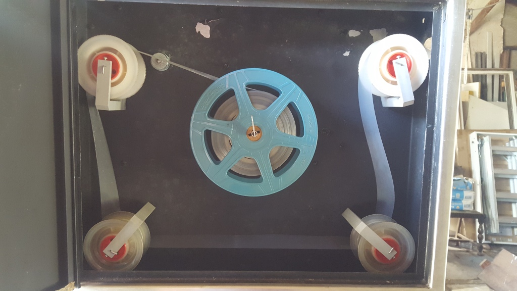
This is the undeveloped, or exposed film, feed cabinet. The exposed film reel is placed onto the spindle, stapled to the transparent film leader and closed. Once the film and transparent tail is wound off this reel the processor automatically stops, allowing the operator to re-staple the transparent film leader and ensure continuous threading of the processor.
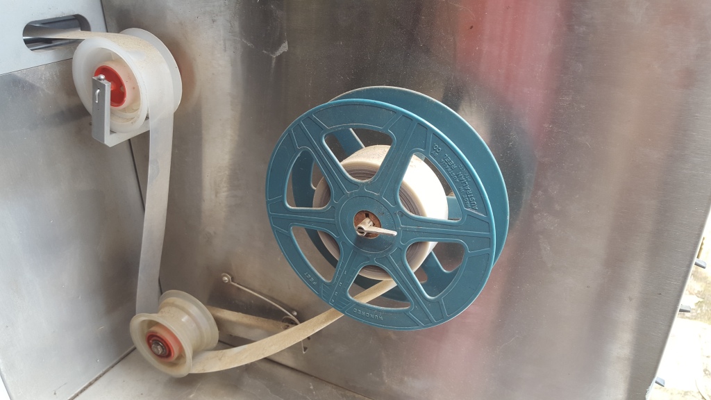
This is the developed film take-up. Once the film leaves the drier it winds onto this reel.
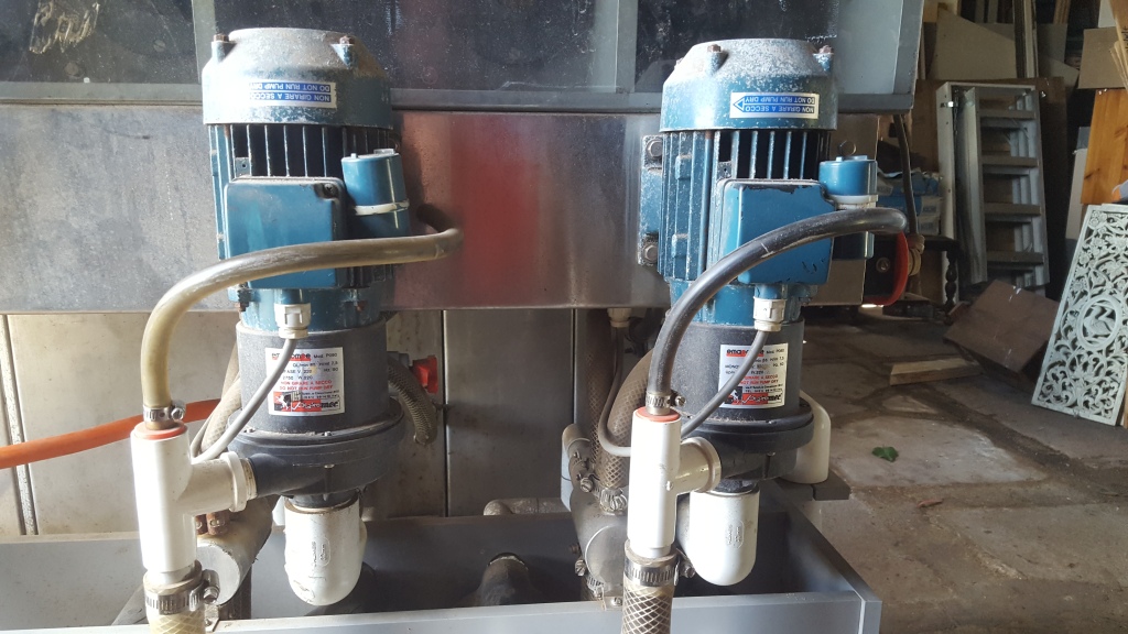
The developer and fixer filter pumps. These run during the process to filter out particles, sediment, or emulsion that may have lifted from the film if it is very old.
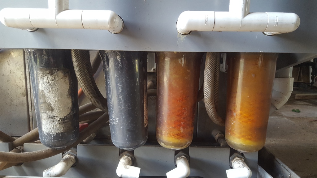
These are the four filters for the pumps. The two on the right filter the developer, the two on the left filter the fixer. These have since been cleaned thoroughly.
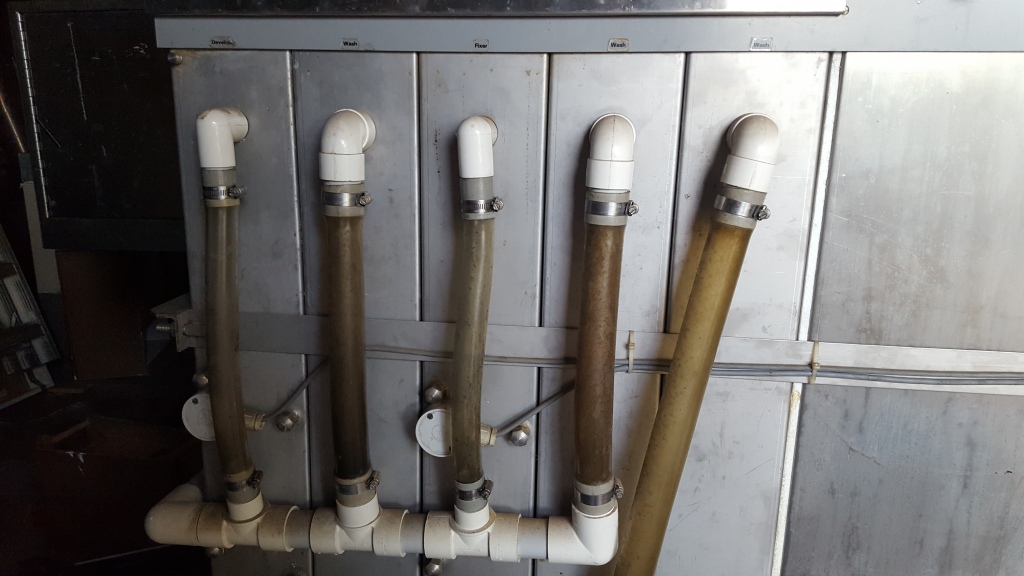
This picture shows the over flow pipes from the top of each tank. Incidentally, as the processor came with now instruction manual, these over flow pipes indicate the maximum liquid level in each tank, therefore indicating with fair accuracy how much chemical and water is needed in each tank, approximately 100 litres.
February 2023 update

This is a variable frequency Drive purchased to run the processor. The processor needs 3 phase power to run, as it is very expensive to get 3 phase wired to a house, converters can be used to convert normal house mains power to run 3 phase electric motors.
Although the VFD successfully activated the processor, several functions were unable to be tested, possibly not enough voltage.
This wiring was done under the supervision of an electrician and close reference to the VFD manual. When doing such wiring, always use protected circuits, in other words, be sure a safety switch is on the electrical circuit.

While we are working on getting the VFD converter to run all elements of the processor, we are using house mains power to run most parts of the processor to maintain, check on running condition, and look for anything that might need repair or adjustment. In this picture the mains earth is looped to the 3 phase connections. This wiring was done under the supervision of an electrician.
March 2023 update
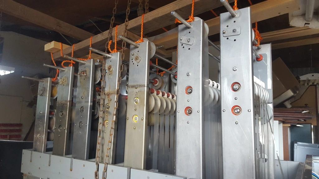
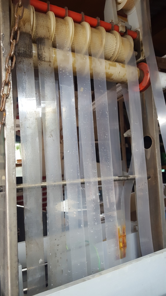
Each tank of the processor has a roller assembly. The transparent film leader threads it’s way through these assemblies as it travels from once process to the next. As the film leader is one piece, from unexposed take-off reel to finished take-up reel, examining one roller assembly requires all come out. Individual assembly extraction will be worked out later.
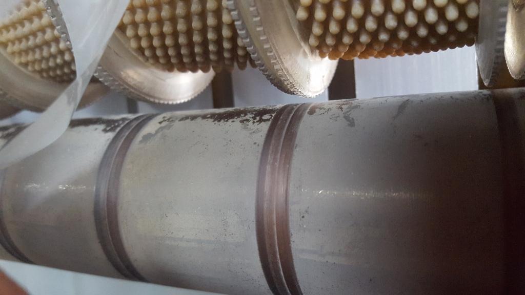
Each roller assembly has a drive roller that the multiple film rollers with nodule rubber tires rely on for turning drive, thereby assisting the film travel without too much tension through the various tanks. in this picture you can see the film rollers are not touching the drive roller. This would mean the take-up reel motor has to drag the film through the processor, greatly increasing likelihood of film breakage. Dec 2023 addition -After receiving advice, the rollers have a spring core, so when under tension with film, then they sit on the drive roller.
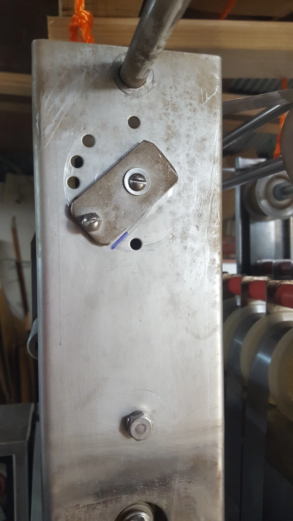

On the side of each roller assembly is an adjusting cam that lowers or raises the film rollers onto the drive roller. The first picture shows a marking prior to adjustment, the last picture the mark post adjustment.

This picture shows that after the roller height cam was adjusted, the film rollers now sit on the drive roller. I am guessing that when the film processor was being used by a lab an annual maintenance check would mean also checking the film rollers are contacting the drive rollers.
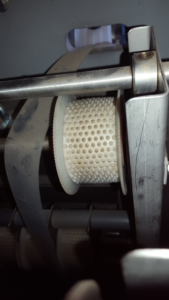
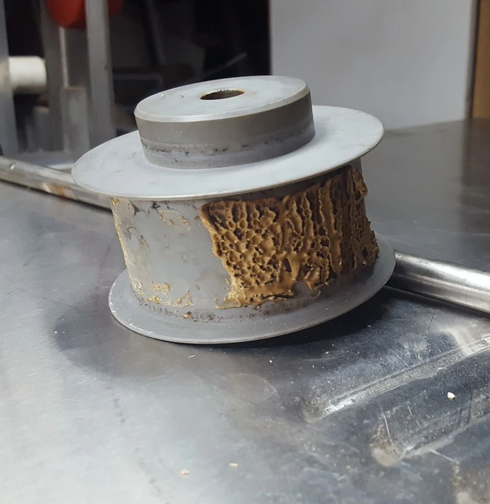
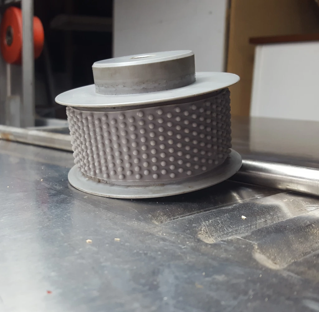
This pictures shows one of the film rollers. Each roller has a soft rubber tire on it’s core. These rollers have soft nodules that provide a semi sticky touch to assist in moving the film through the various vats of chemicals. The nodules only touch the underside of the film, not the emulsion. over time these nodule tires, unless regularly cleaned, will have chemical build-up and may harden or crack and degrade. A New York manufacturer: https://www.jjshort.com/ specialises in making such soft rubber tires and other rollers for film processing machines.
August 2023 update
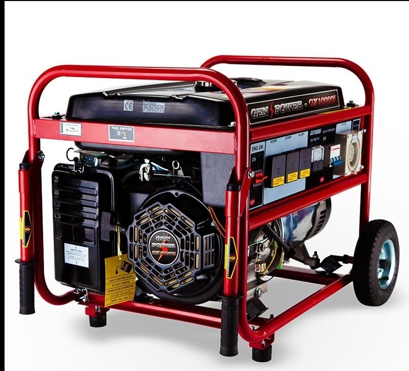
This picture shows the newly acquired 3 phase 11 Kva generator. (this is a stock shot, our generator is second -hand and looks terrible… but should run just as well) After researching the viability of another VFD, as above, and the ongoing issues of not having enough voltage to the machine, I decided to buy a generator with a 3 phase output. We have not tested it out yet, but I think this will be our best shot.
The other alternative to using a 3 phase power source would be replacing some of the processors motors with single phase motors, and wiring the motors in tandem to 240 volts. Not a hard process, just quite fiddly and would require lots of trial and error testing
October 2023 update
So the generator was fully serviced and is running very well. The film processor was plugged into the generator and most of the generator’s motors ran. The good news is that the processor will run on the generator happily, despite the generator putting out small fluctuations of voltage (common with generators) The generator was unable to power all of the processor’s functions, as the more I switched on, the more the generator voltage dropped. So, I next disconnected the items I will be replacing: the 3 phase vacuum motor and the 3 phase heater fan motor and elements. I disconnected the two water pumps as I intend to wire these separately and run them independently of the film processor’s power supply. Next I ran the film processor with the generator and all the remaining functions worked. So the developer and fixer heaters were warming up, and the main drive motor worked well at all speeds.
I have started replacing roller rubbers, I was delayed as I had to build a rig to extract one roller rank at a time. As per the photo.
November 2023 update
So I attached a 20 meter 3 phase extension lead so the generator noise will be further from the processor. I replaced a roller tire, see pics. I also cleaned and adjusted the 1st wash roller rack. I will not be exhaustively cleaning the processor until it is ready to process film. I will still clean as I am going about other jobs, but the main priority for now is getting it running, all functions working. I dismantled one of the pumps and de-seized it, but it still will not run. As can be seen with the picture above and to the right, the leader broke, from some very old rusty staples so I hade to re-thread with feed leader and re-join it to the tail of the broken off leader. That was a painful job.
January 2024 update
Both new water pumps have been installed, just needing to buy more plastic elbows and other bits and pieces to finish off fixing up the ‘wet’ section. I made some short videos of the processor running, see below. All the roller assemblies have been adjusted and cleaned. I am still working on power usage setups, for instance the vacuum motor runs well.
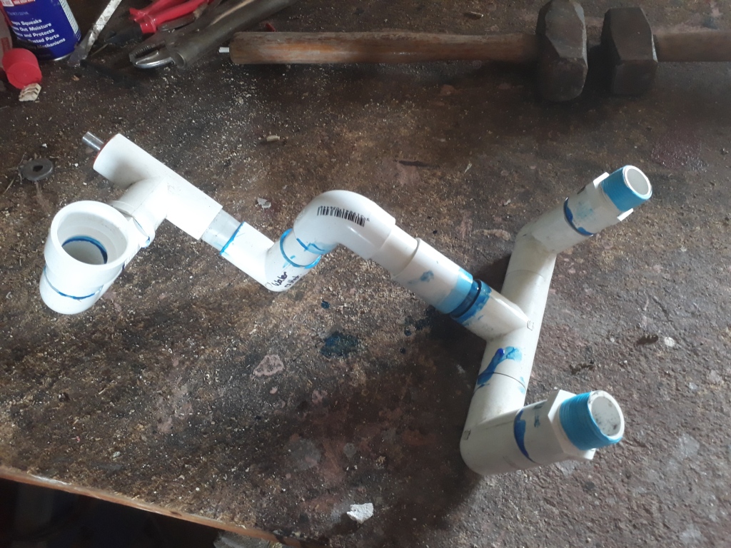
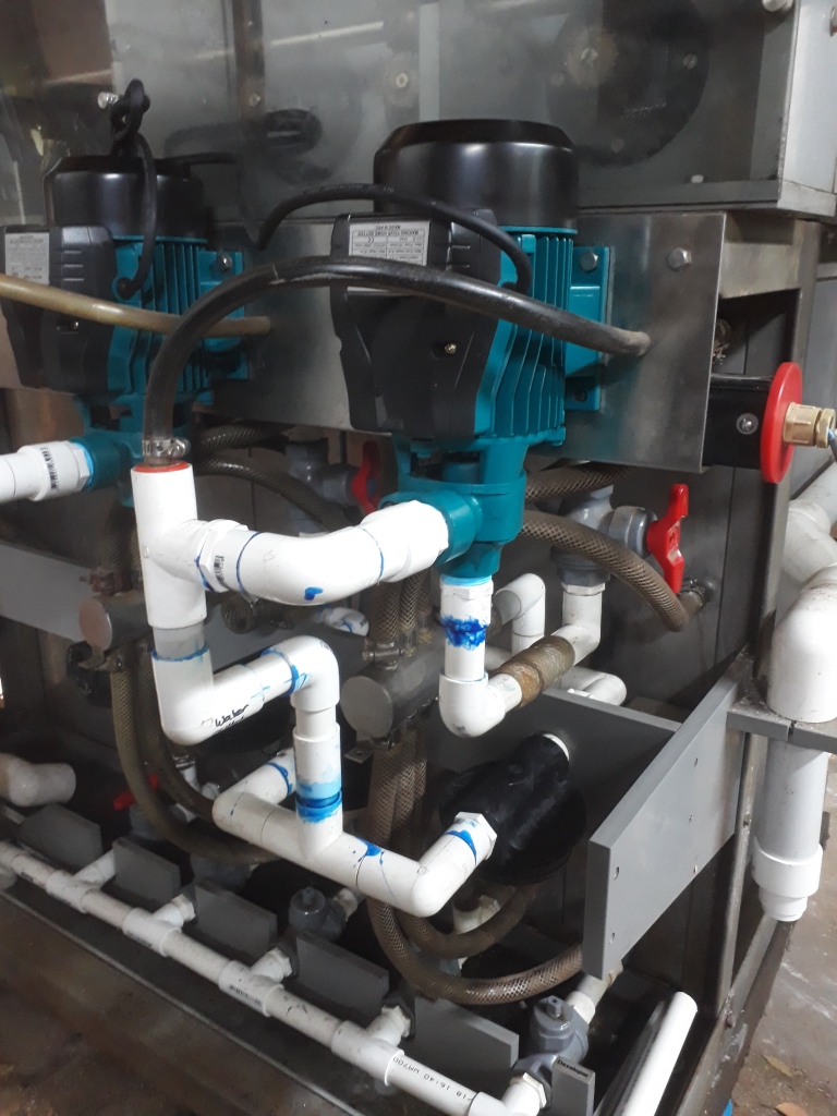
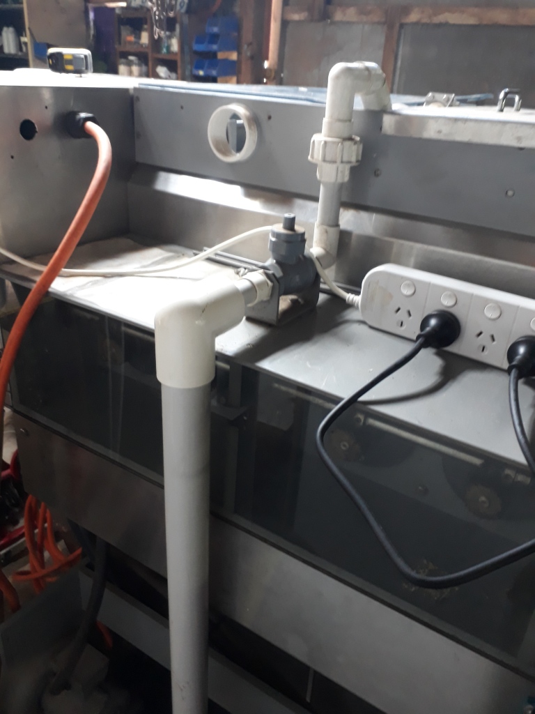
This plumbing creation connects the filters to the air valve and water pump outlet. I decided to stick with the original design of using solid plastic instead of easier to use large diameter hose. The second picture shows the completed setup with new water pump installed.
February 2024 update
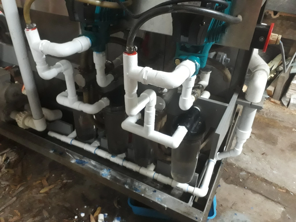
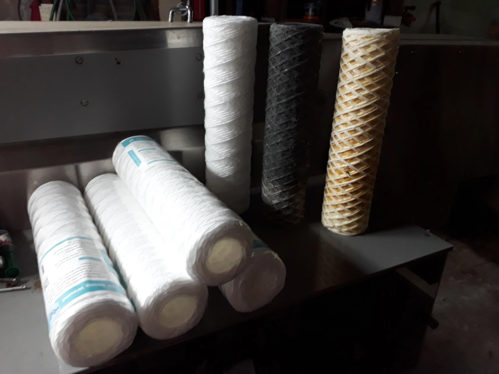
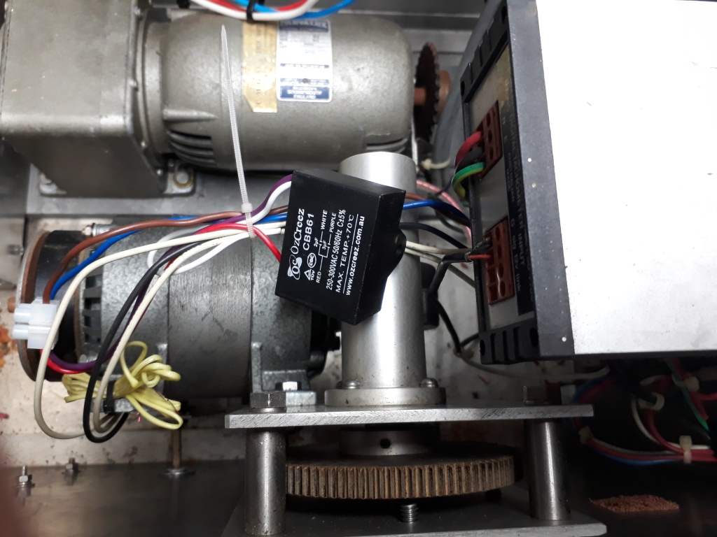
So the myriad of plastic pipes has been painted to look better. New filters arrived and fit well. From the photo above you can see the very dark filter that was used for the fixer, and the yellowish one of the developer. The next photo is of the capacitor that was replaced with a quality local item.
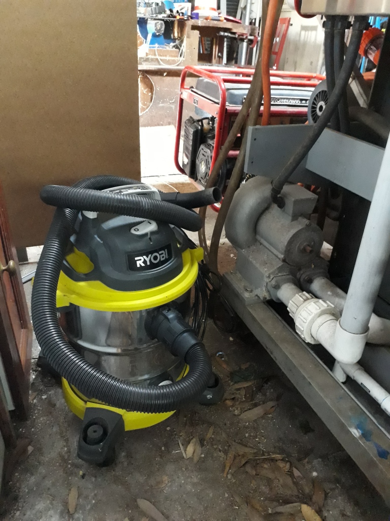
The next part will be replacing the old 3 phase vacuum motor that, via the plumbing piping, used to suck remaining water off the film as it departed the last water rinse vat and into the drying vat. By adapting the wet and dry vacuum to the same piping I can achieve possibly better results than trying to re-commission the original motor, which when tested did not suck at all.
The dryer rack roller, when tested for smoothness, was found to have old and stiff bearings. These have also been replaced.
I also ran the processor to test how long it would take to process film that required different development times. Although I had no particular film in mind when running the test.
10 minutes developing time = set dial to 4 Feet Per Minute (untested)
9 minutes developing time = set dial to 5 Feet Per Minute (untested)
8 minutes developing time = set dial to 6.2 Feet Per Minute
7 minutes developing time = set dial to 7 Feet Per Minute
6 minutes developing time = set dial to 8 Feet Per Minute (untested)
5 minutes developing time = set dial to 9 Feet Per Minute (untested)
COMING UP…..
Attach the vacuum cleaner to the vacuum piping and test with wet film, measuring effectiveness. Checking over the heater fan and researching it’s replacement. Working on adapting a 1000ft film magazine to be attached to the processor to better facilitate processing 400ft of undeveloped film, and attaching at least 300ft leader to the tail to ensure continuous leader remain threaded in the processor.
LONG TERM GOALS….
Working out acquiring chemicals to commence first run. Repairing light seals. Acquiring 100 litre air tight drums to store used developer and also store fixer for later silver recovery before disposal.
December 2022 video clips
This sped up short video shows me unloading the very heavy processor. Although it seems quite small as processors go, I had to hire a heavy duty trailer and 4WD ute to tow it.
February 2023 video clips
January 2024 video clips
DISCLAIMER:
This is a Copyright Disclaimer under section 107 of the Copyright Act of 1976, allowance is made for “fair use” for purposes such as criticism, comment, news reporting, teaching, scholarship, education and research. Fair use is a use permitted by copyright statute that might otherwise be infringing.
Fair Use permits limited use of copyrighted material without having to first acquire permission from the copyright holder. Fair use is one of the limitations to copyright intended to balance the interests of copyright holders with the public interest in the wider distribution and use of creative works by allowing as a defense to copyright infringement claims certain limited uses that might otherwise be considered infringement.The creator of this website declares that information and photographs copied from other websites and placed here is solely for the purpose of education and research. The creator of this website does not earn money from information published here. The creator of this website always references, where possible, the original creator of work that is published here.
If any person wants to dispute this, and/or believes the creator of this website has infringed on a person’s copyrighted creative material, please email me at mishkin.film@gmail.com
